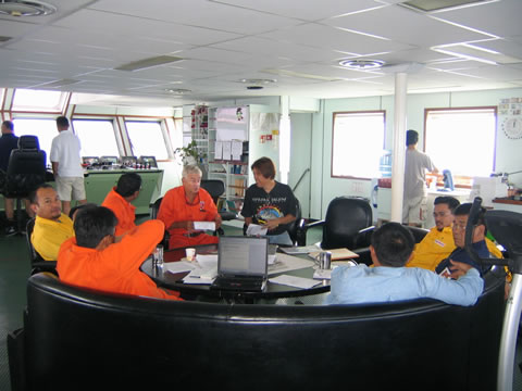
Part of engineers jobs is to plan, execute and present the operation progress to client every morning. Picture taken during Daily Progress Meeting @ DPDSV bridge.
ENGINEERS TRAINING CHECKLIST
Describe the use of the equipment below and understand how it works, and what are the necessary procedures and/or precautions that are required for its operation, if any.
Schematics/Sketches/Layout of equipment if available
- Installation Equipment
- Communication Equipment
- Navigation Equipment
- Positioning Equipment
- Beacon or Transponder on Anchor
- Support Facilities
- Diving Facilities
- Survey Equipment
- Safety Facilities
- Pulling Winches
- R.O.V System
- D.S.V
- Anchor Handling Capabilities of Vessel
- Anchor Tracking Equipment
- Acoustic Positioning Systems
- Radio Positioning Systems
- Design of Padeyes Lifting Slings
- Hooks
- Shackles
- Offshore Rigging Platforms
- Loadout Stability
- Seafastening/tie down details
- Transportation Analysis.
- Environmental Conditions
- Wind Direction, Force
- Wave Magnitude
- Draft at Loadout Quay.
- Transportation and Loadout
- Barge Arrangements/layout
- Seafastening & Tie-Down Design
- Tow Analysis
- Specifications Used
- Rigging Procedure for All Types of Lifting.
- Sling and Shackle Rigging System
- Certification and Testing of Sling and Shackles.
- Barge Transportation and Seafasterning Analysis and Tug Boat Bollard Pull Capacity.
- Seafastening Design Calculations.
- Barge Strength and Stability Checks
- Seafastening Drawings
- Seafasterning Materials (MTO) and wastages and over lengths.
- Towing Bridle Selection/Design and Calculations.
- Route Survey/Map and Identified Shelter Locations.
- Lifting Rigging Arrangement.
- Third Party Certification for Sling and Shackles.
- Calculation of Sling Analysis, Sling Tensions (3 out of 4 slings operative)
- Sling/Shackle Safety Check.
- Jacket Structural Integrity Check.
- Seafastening Cutting Sequence
- Lifting Criteria
- Derrick Barge/Transportation barge setups
- Jacket Tilt Angle During Lift.
- Lift Radius, Lift Weight and Required Hook Height Super Imposed on Crane Lift Charts.
- Jacket Weight, Displacement and Buoyancy Calculations.
- Upending Rigging Arrangement.
- Upending Sling Tension per each Upending Step.
- Upending Sling and Shackle Safety Factor.
- Upending Padeye Check.
- Sling/Shackle 3rd Party Certification.
- Controlled Flooding Sequence/Procedure of Jacket Legs/Buoyancy Tanks (if any).
- Hook Radius, Load and Height at Each Upending Stage Superimposed on Crane Lift Chart.
- Jacket Angle on Each Stage of Upending.
- On-bottom Weight Calculations and Madman Adequacy Check.
- Medical Clearance at Each Upending Stage.
- Pile Driving Engineering Report.
- Stability of structure against overturning during piling. Verify pile stick-up length for pile hammers.
- Method of pile lifting and upending. Calculations to prove methods do not overstress piles.
- Pile refusal/acceptance criteria based on expected pile stress and designed ultimate bearing capacity of pile.
- Predictions.
- Pile self penetration (Self weight and with first hammer in proposed piling sequence)
- Pile Driveability analysis by specialist Geotechnical Engineer.
- Recommendation:
- Hammer to be used (from self pen. To target pen)
- Pile Driving sequence.
- Retrieve Procedures – premature refusal of insufficient bearing capacity.
- Soil Resistance to driving taking into account plugged conditions as appropriate.
- Hammer blow count w.r.t penetration.
- Effect of delays in driving.
- Effect of variation in hammer efficiency based on typical range of hammer efficiencies.
- Pile stresses during driving.
- Effect of utilization of driving stress if required.
Above predictions to be made for the range of hammer proposed.
- Specialist geotechnical consultant proposed.
- CV of personnel proposed for pile monitoring. (Yes, all subcontractors Personnel must be properly vetted)
- Pile monitoring equipment spread.
- Data analysis and interpretation methodology.
- Operational aspects of installing instrumentation, data acquisition and removing instrumentation.
- Equipment/Instrument calibration.
- How pile monitoring data will be used to control pile driving.
- Within 1 hour after driving.
- Pile driving analysis print out.
- Pile adequacy assessment – after driving to target penetration after refusal at any other penetration.
- Recommendation of remedial action, if any.
- Summary s.o.w.
- Pile/Conductor adequacy conclusion with support calculations.
- Result of PDA pile/conductor Monitoring.
- Hammer preference summary with hammer nos for tractability.
- Pre-installation analysis/procedures for interpretation of field measurements.
- Predicted vs. Actual pile/conductor Driving behavior.
- Instrumentation + Monitoring Equipment + Procedures + Calibration reports + Correction factors.
- Log kept by pile monitoring engineer highlighting significant events during pile driving.
- Lifting rigging requirement.
- Sling/shackle certification from 3rd party surveyor. (
- Topside installation engineering report.
- Calculation of sling, padeye orientation based on latest COG.
- Calculations of sling tensions assuming 75/25 load distribution to opposite fair of slings.
- Sling/shackle safety factor.
- Padeye strength check.
- Deck structural lategnity check (if required)
- Limiting criteria for lifting.
- Derrick + Transportation Barge Set-ups.
- Attitude of topside during lift (Ë of lift)
- Lift radius, weight and required hook height superimposed on crane lift chart.
- Upgrading lift analysis.
- Understand the Anchor Pattern.
- Understand how to run anchors and identify the sequence.
- Most importantly know your supporting spread.
- Anchor Handling No. 1
- Anchor Handling No. 2
- Supply Boat
- Crew Boat
- Jacket Transportation Barge or Launch Barge and its tugboat
- Topside transportation Barge(s) and its Tug Boat
- Pile Transportation Barge + its Tug
- Conductor Transportation Barge + Its Tug
- Platform appurtenances Transportation Barte + Its Tug Boat
- Understand the Anchor Catenary table.
- Anchor Numbering of the Barge.
- Anchor Accessories i.e. Mid line bouy, Penant Wire, Norwegian buoy, Yokohama Fenders, Type of Anchors
- Detailed anchor handling procedures and anchoring patterns with due to consideration to avoid damage to existing facilities by anchors and / or anchor cables.
- Echo soconder
- Side scan sonar.
- Pipeline.
- Theodolite.
- EDM (complete at prism)
- Handheld GPRS receiver
- Level and staff
- Flugate compasses
- Mean sea level measurement Device
- Acoustic Tracking system.
- Data processing equipment.
- Manpower Supply. Typically some crew are supplied by 3rd party. i.e. construction crew, rigger, marine crew and even the PMT it self. By knowing this, giving you and ideas of the ‘politics’
- Diving Subcontractor
- ROV Subcontractor
- Auto Welding Subcontractor
- NDT Subcontractor
- Marine Spread(s)
- Main Work Barge Owner
- MWS (Marine Warranty Surveyor)
- Weather Forecast
- Hammer Subcontractor.
- ILT Subcontractor.
- GeoTech Subcontractor.
- Major Rigging and Slinging Subcontractor
- Communication / Internet Subcontractor
- Catering Subcontractor.
- Painting Subcontractor
- Automatic Welding Subcontractor (for Pipeline)
- Field Joint Coating Subcontractor (for Pipeline)
- Uniform deck load longitudinal bulkhead
- Line load along transverse bulkhead.
- Point load along longitudinal bulkhead
- Point load along transverse bulkhead.
- Point load at intersection and transverse bulkheads.
- Line load
- Actual Ballast Pump Capacity (built-in + supplementary ballast pump)
- Level and straighten of skid beams/launchways.
- Towing bridle and associated fittings.
- Function test on launching system
- Rocker beam rotation.
- Function test on all navigation aids.
- Pre-post installation survey.
- Lift Jacket-check diaphragms intact.
- Upend jacket.
- Place jacket.
- Install pile.
- Lift + upend files.
- Stabbing and driving sequence procedures.
- Monitor pulling activity.
- Drive piles to target penetration.
- Pile Driving Records.
- Hammer used
- Hammer monitoring data
- Pile identification.
- Blow count vs. penetration
- Time
- Pile monitoring data.
- Reason for stoppages if any.
- Pile restrict test.
- Soil resistance to driving.
- Magnitude of maximum pile stresses during driving.
- Hammer blow for foot of penetration.
- Hammer stroke.
- Hammer blow rate.
- Hammer efficiency.
- System efficiency.
- At end of driving if pile meets acceptance criteria.
- Find blow count for fast of penetration
- Hammer and system efficiency.
- Soil resistance to driving
- If pile/conductor does not meet acceptance criteria at target penetration depth provide a recommendations on remedial action.
Pile monitoring during the restrict test provide.- Final blow count per foot of penetration.
- Hammer and System efficiency.
- Soil resistance to driving.
- If pile meets premature refusal provide.
- Final blowcount per foot of penetration
- Hammer and System Efficiency.
- Soil resistance to driving.
- Recommendations of remedial action.
- Conductor driving
- Hammer used
- Hammer monitoring data.
- Conductor identification.
- Blow count vs. penetration (blow/ft)
- Time
- Conductor monitoring data.
- Reason for stoppages if any.
- Conductor and Hammer Monitoring.
- Boatlanding and Riser Guard Installation.
- Topside Installation.
- Cut jacket transition.
- Lift, Low and Place Topside.
- Micellaneous installation
- Stairways.
- Grating
- Miscellaneous platform.
- Conductor spools
- Rigging platform removal.
- Vent Boom Installation.
Yes, this one of the most powerful tools for Field Engineers to monitor, plan, communicate and execute the works also. I’ll share some typical Action list for your reference and the list will be added from time to time. Should you have samples you want to share, please email it to us.


